The Fun Part
After spending weeks working on each component, sanding them, staining them, sanding them, staining them, sanding them, et cetera, et cetera... I was finally onto the exciting part.
Chordophones Assemble!
My process of assembly wasn't extensively thought out when modelling it on CAD, and I would have made it a bit simpler to put together and take apart if I did it again. That being said, I still kept it in mind and ensured no huge pieces had to be permanently glued in place and the keys and jacks would both (hopefully) be able to come out with ease. Some pieces did have to go in first though.


The balance beams and pins were first to go in. The rear pins were just lengths of wire siliconed into the too large holes while the fore pins were comfortably fixed in with AB. The assembly on the left were guides to hold two levers in place which were responsible for the octave shifts. I didn't speak about this before, but for my final model I tried a different mechanism to lift the octave shifts. This was possibly a bad idea as I had never tried it before, but on paper, it should work. More on that later.

Test fitting the keys. It was here I realised i was too generous with the tolerances between the keys and they moved from left to right a lot. The slots for the fore and rear balance pins were too wide, also creating a movement issue. Oh well! hard to get everything perfect.


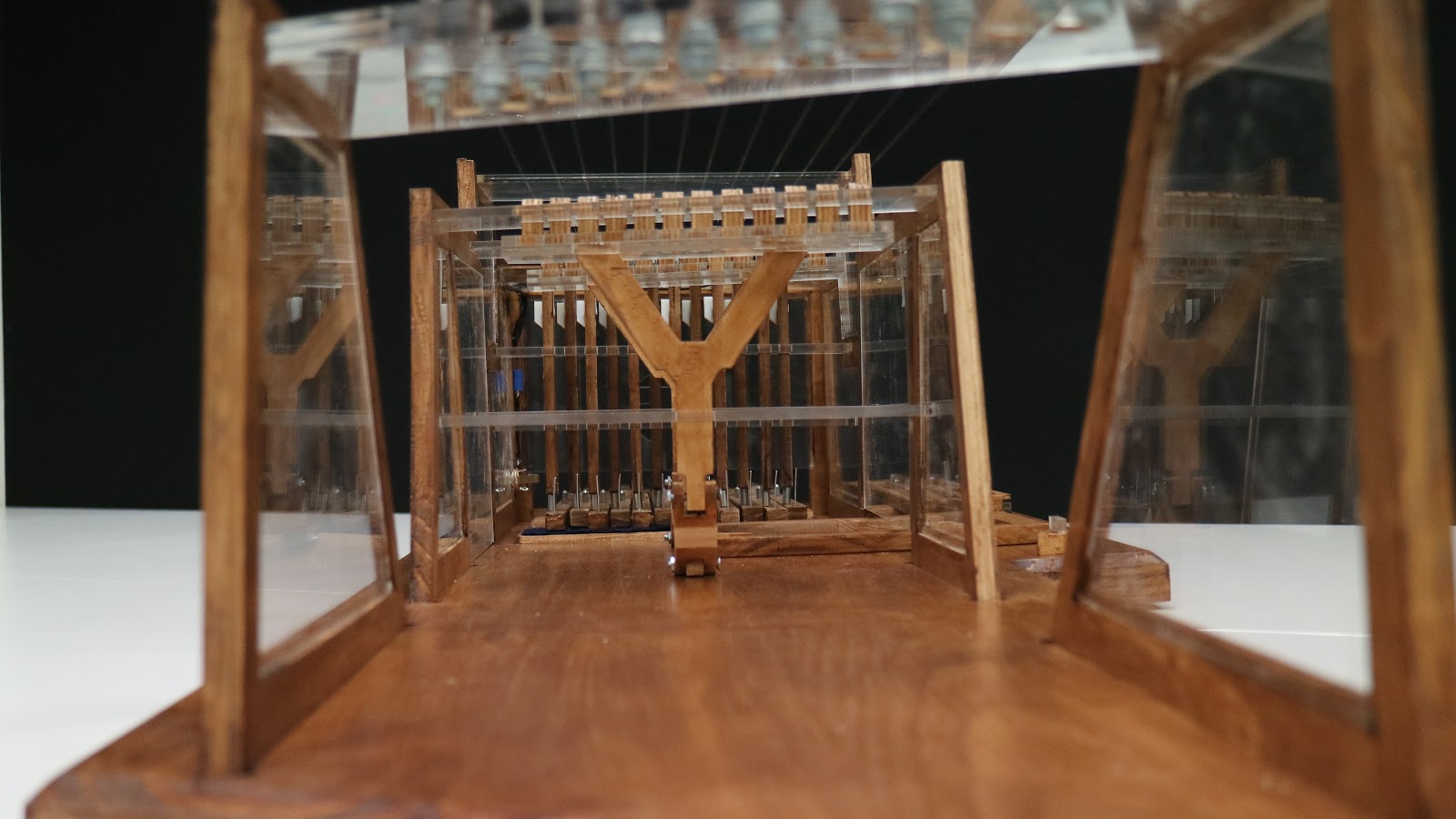
These were the octave shifts. I glued in the Y shape first and then rested the acrylic piece over two tables so it was level as I glued in the 24 frets. I used the acrylic registers to ensure the frets were all glued in perfectly enough that they would rise and fall through the register on the final assembly.


The pickups fitted in quite nicely, and I cut the ends off to wire them all together in parallel. A feeling of sheer horror filled me when I saw there was only one wire when I had stripped the insulation off. I need two wires! I was expecting two wires! I quickly jumped on my skateboard and went down to Allens to see if they could help. Nope, he's just a shop clerk, what does he know about the internals of piezo pickups. While I was stressing, I fiddled around with the part I had cut off and noticed that there was a second wire, in a clear tube, in the middle of the other wire. THANK THE HEAVENS MY FAITH IN SCIENCE WAS RESTORED.
Getting access to these wires and soldering them together was messy, but pretty straightforward.


The Jack was on a different component as the pickups, so I bought a plug from jaycar (which was the crappiest design in the world or I'm just an idiot). But I got it to work and successfully tested it on an amp with no worries - After i figured out which of the wires from the pickup was positive and which was negative.
I should also note here that the laser cut windows which sit inside the wooden framework were all cut without a hitch (some parts didn't have paper on them because Mods sold me some of his acrylic, and these parts had some flame scarring on them, but they washed off with relative ease using a stain removal spray). The windows were all glued into place and I became more confident that the framework would be rigid enough to support 12 strings.


Felt was added to the rear balance beam to help silence the noise of the keys hitting the wood and the octave shift levers were put in place.


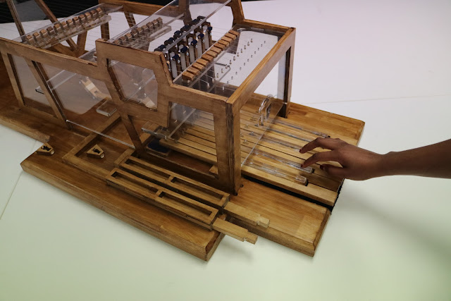
All the registers and octave shift components had to be put in place before any of the framework could attach to the base. This was awkward, but surprisingly, wasn't the end of the world. With a bit of work, the left and right frames aligned with their respective slots on the base.

While trying to align the front frame with its slots, I had to try sand down one of the ends. This ended in a tragic snap.

I tried gluing it back together, but with no access to a large clamp, and no time to spare, it eventually broke again later on.
Once all the framework was aligned, and I triple checked all the acrylic registers were in place AND the correct orientation (nothing is symmetrical), I began the painful task of beating the frame into their slots like a brute with a mallet.


It took about two hours of evenly smashing my hard work before the framework descended 30mm into the base. More time was spent on the right side which we sudo-fixed earlier on in the project.

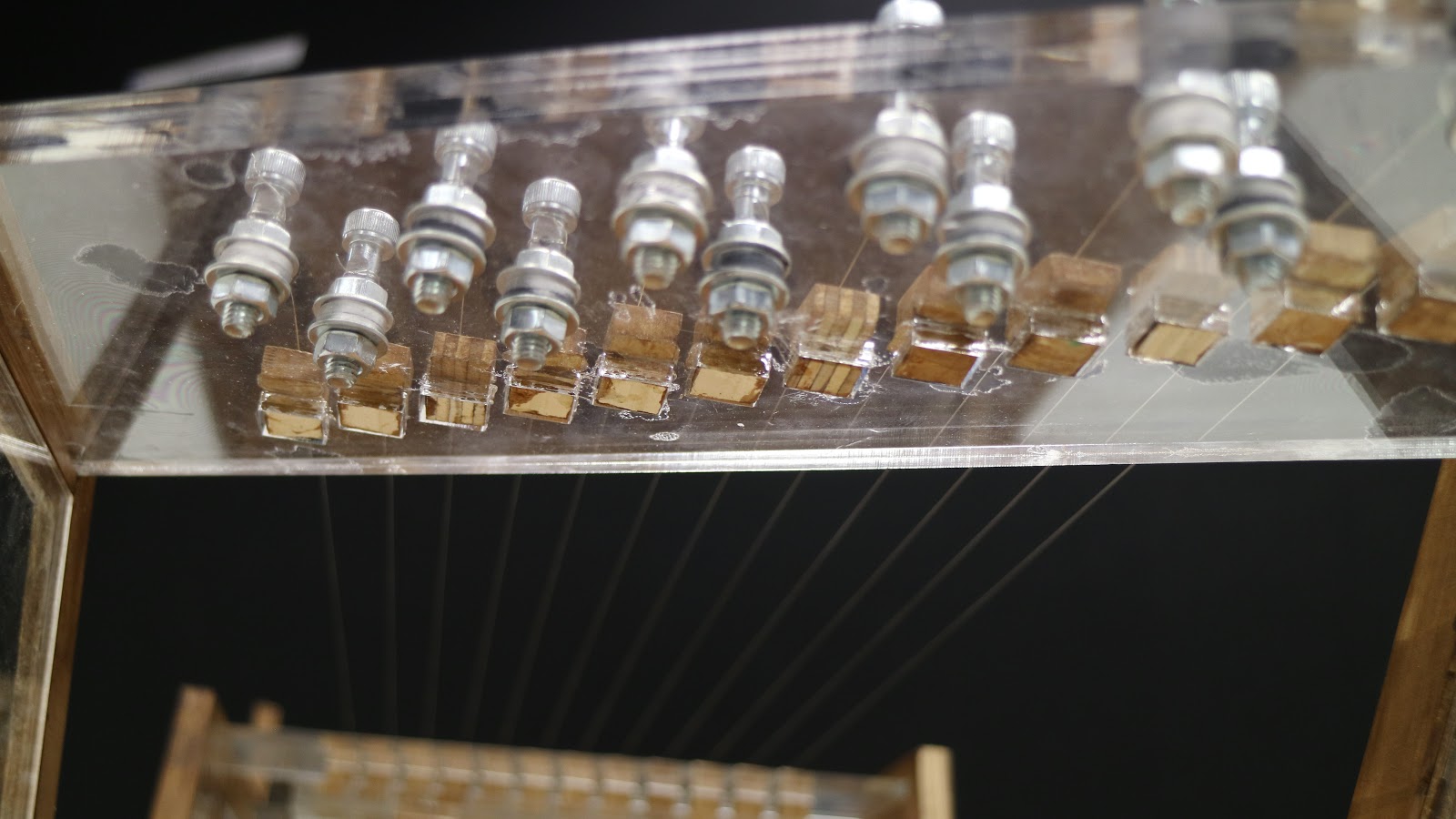
It was at this point where I finally was able to test out my tuning pegs properly. The steel peg was fit tightly into a 12mm length of rubber hose, which fit tightly into a 12mm deep hole in the acrylic uhh... lets call it a rear bridge.
The tuning pegs didn't work.
The friction might have been enough to keep the peg from unwinding, but the 12mm depth was not enough. Maybe if the pegs were 30mm longer it might have worked, but I had to find a quick solution. For Prototype 3 I used a bolt and two nuts, one on either side of the platform to prevent it from unwinding. Bolts and nuts were not ideal aesthetically, but they'd have to do at this point. At Bunnings I found some nice looking M6 allen bolts. These fit into the rubber hose which compressed under the tightening of the nuts. The compression against the inner walls of the acrylic hole meant the nuts weren't tightening straight onto the acrylic sheets, which seemed like a positive.

The flat faces didn't prove to be enough to tight the strings off however and I ended up drilling holes in each one.


I broke 2 drill bits. That is why some have different size holes.
The next issue I found was to do with the octave shifts. The Hail Mary mechanism worked (I know, I couldn't believe it either) but the frets didn't move high enough to contact the strings. My solution was to extend these hinge parts. It was really the only solution I could think of considering the fret assemblies were now fixed in place.


This solved the problem, for the most part, but made it very hard to push the octave shift levers, I guess the angle the modified hinges were on was less that 45 degrees making it hard to transfer the horizontal motion to a vertical motion. Later on, this stiffness resulted in the longer lever snapping in two places. I glued it back together with epoxy but perhaps a steel component was in need here.


Another issue. When the key was pressed and the jack lifted to its maximum height, the plectrum sat just beneath the string. It needed another 20mm or so of movement for it to properly pluck past the string.
I saw two solutions to this, increase the length of each jack, perhaps blue gluing a 20mm block at the bottom of each one, or, lower the floor of the key bank so the keys had a further downward travel.
I elected to chisel out the floor because it seemed easier.


I bought a set of chisels for this task. After removing this much, the keys still didn't travel down far enough, so I removed some more and glued felt over it to hide the mess and also soften the noise.


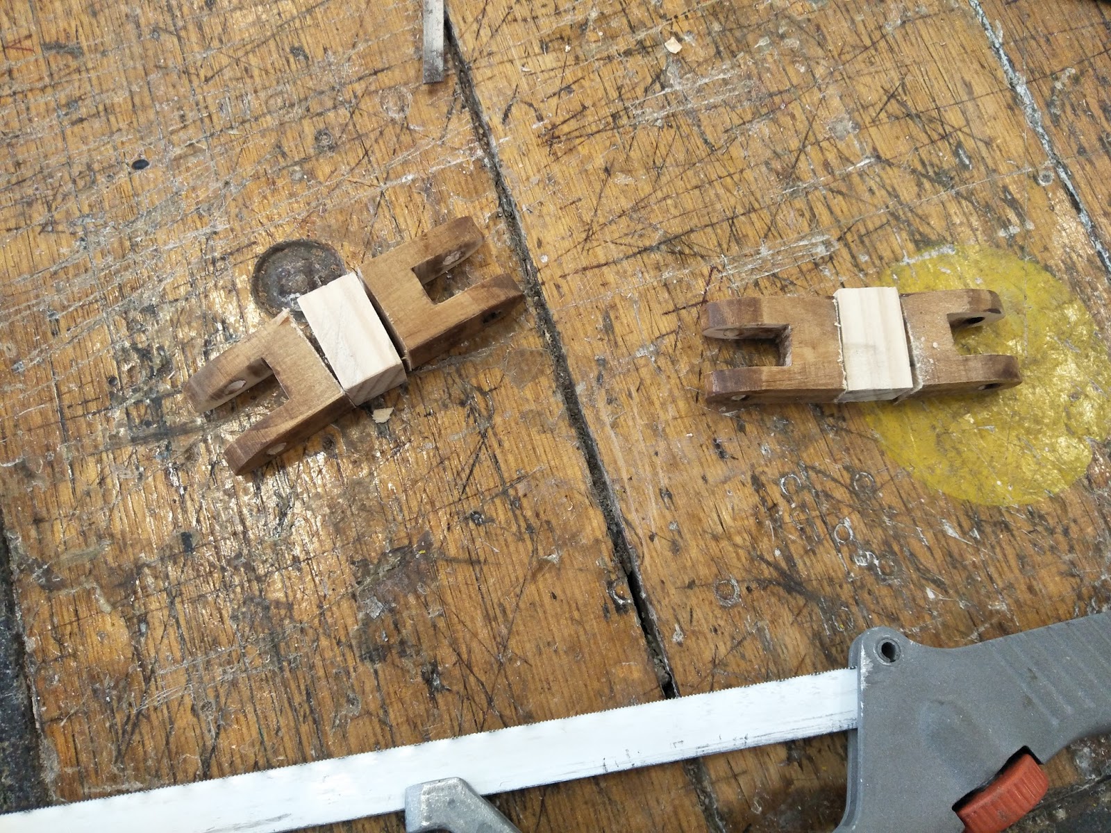
Aaaaaand, it still didn't cut it. Of course not, I had to remove 20mm of material and I took off maybe 8 or 9 at most. So I went for plan B, lengthen the jack. Finding 8mm thick blocks of wood seemed tedious and impossible on a Sunday in the DB317, but I remembered that a few traditional harpsichord jacks looked like this
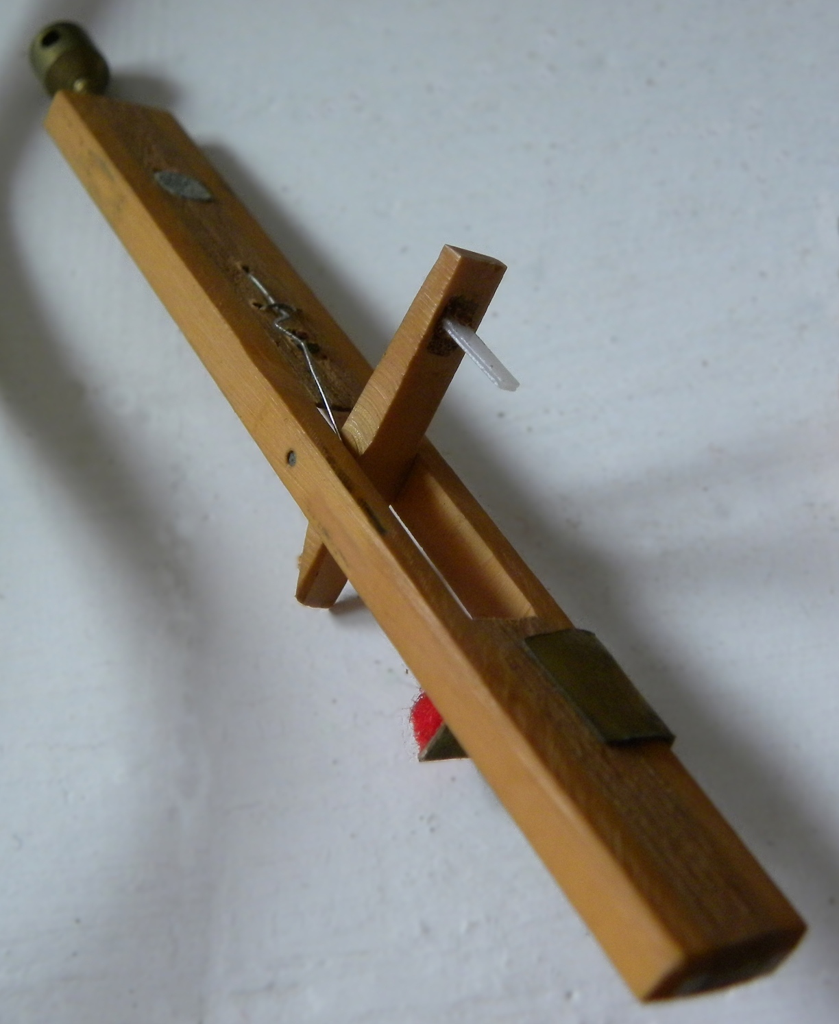
There's a metal pole at the bottom of the jack (top left corner) which registers to a slot on the key (I didn't include this in my design unfortunately). This inspired me to use 20mm lengths of 6mm steel rounds to prop up the jack to the desired height.


This solved the problem and the plectrum was now able to pluck the string! Victory!
I moved onto assembling the rest of the jacks, which included sanding down the 3D printed tongues (white part that pivots and holds the plectrum) so they fit comfortable in the jack and rotated back and forth freely. I started to make the plectrums from HIPS again, but the strings we situated a lot closer to the jack now than in the prototype, which didn't allow the plectrum to be long enough to bend. This resulted in a lot of force needed to press down on a key to make a noise. But I hooked it up to the amp (which worked no worries, I might add), and I noticed even the slightest touch of the strings were picked up and amplified. SO my solution to HIPS being too rigid? Use paper! I folded a small strip of paper enough to slot into the gap I left in the 3D printed part (so I could change out the plectrums later on) and tested the sound. Paper was perfect! Rigid enough to make a noise come out the amp and flexible enough so the keystroke needed barely any pressure at all.


I never implemented a spring to assist the tongue to return to it's original position because they did so without one. A spring would definitely be an improvement to the jack so it's something I intend to do at a later date.
While sanding the tongues I sanded a bit too far and ended up seeing red on the sand paper suddenly.

But no time for bandaids...


These allen bolts worked exceptionally well for tuning. Once the lower nut was as tight as it could be, I could tighten the bolt without it trying to untwist. I used 11 gauge electric guitar strings for the higher 8 notes and 13 gauge for the lower 4, just to relieve a bit of tension for the longest strings.
The tuning pegs worked, the jacks worked, the plectrums worked, even the octave shifts worked. They took a lot of force to engage but they worked. I actually couldn't believe myself at this point. 10 weeks ago I would never have thought I'd product this model. Even through my whole build process, the image in my mind of the end result wasn't nearly as good as the actual end result. Which is a very unfamiliar experience.
I'm very satisfied with myself. I feel like I challenged myself to see if I was as clever as I thought I was. Challenges are good, they teach us so much about what we can do, and what things need work. If I were to chose some of the areas I need to improve on after this project would for sure be based around getting a high quality finish. I began the project putting in a lot of time and delicacy to get the pieces looking nice, but I really should have spent more time sanding EVERY face of EVERY component. This would have made the varnish/stain go on easier and maybe wouldn't have left such a gross fake tan effect. The were parts with globs of varnish built up, areas with glue clearly visible through the acrylic, the frame broke in 2 places while assembling but that was to be expected. By me at least.
If the slots in the base for the frames were just a quarter of a millimeter wider, It might have saved a lot of hammering.
Also the registers which hold the jacks in place could do with a tighter tollerance. The 8x15mm jacks were passing through 8.5x15.5mm rectangular holes in the registers. This gave them too much wobble and they sometimes pass the string without touching it.
But in retrospect, this is the best thing I've ever made. I have a bad habit of beginning extremely ambitious projects (daft punk helmet, 3 separate attempts) and abandoning them halfway through. But this Uni degree has forced me to stick to my guns and finish. That terrible, dreadful, constantly looming deadline really drives a man like nothing else. I don't know who's reading this blog but I'd really like to thank Dan and Andrew for all the advice they gave me down the track. Andrew had some really good ideas which carried into the final design and Dan gave me nothing but encouragement despite my idea being extremely ambitious. Gordo and Toby in the workshop are miracle makers, and I owe them a lot for all the help they gave me. Even Mac was helpful and had some great ideas. This has so far been a really enlightening course and it was throughout the duration of this project that I really got what I joined Product Design for.


That's all for now. Thanks for reading.
-Luke Timpani
I saw two solutions to this, increase the length of each jack, perhaps blue gluing a 20mm block at the bottom of each one, or, lower the floor of the key bank so the keys had a further downward travel.
I elected to chisel out the floor because it seemed easier.


I bought a set of chisels for this task. After removing this much, the keys still didn't travel down far enough, so I removed some more and glued felt over it to hide the mess and also soften the noise.


Aaaaaand, it still didn't cut it. Of course not, I had to remove 20mm of material and I took off maybe 8 or 9 at most. So I went for plan B, lengthen the jack. Finding 8mm thick blocks of wood seemed tedious and impossible on a Sunday in the DB317, but I remembered that a few traditional harpsichord jacks looked like this
There's a metal pole at the bottom of the jack (top left corner) which registers to a slot on the key (I didn't include this in my design unfortunately). This inspired me to use 20mm lengths of 6mm steel rounds to prop up the jack to the desired height.

I cut grooves into the bottom of each jack about 2mm deep.
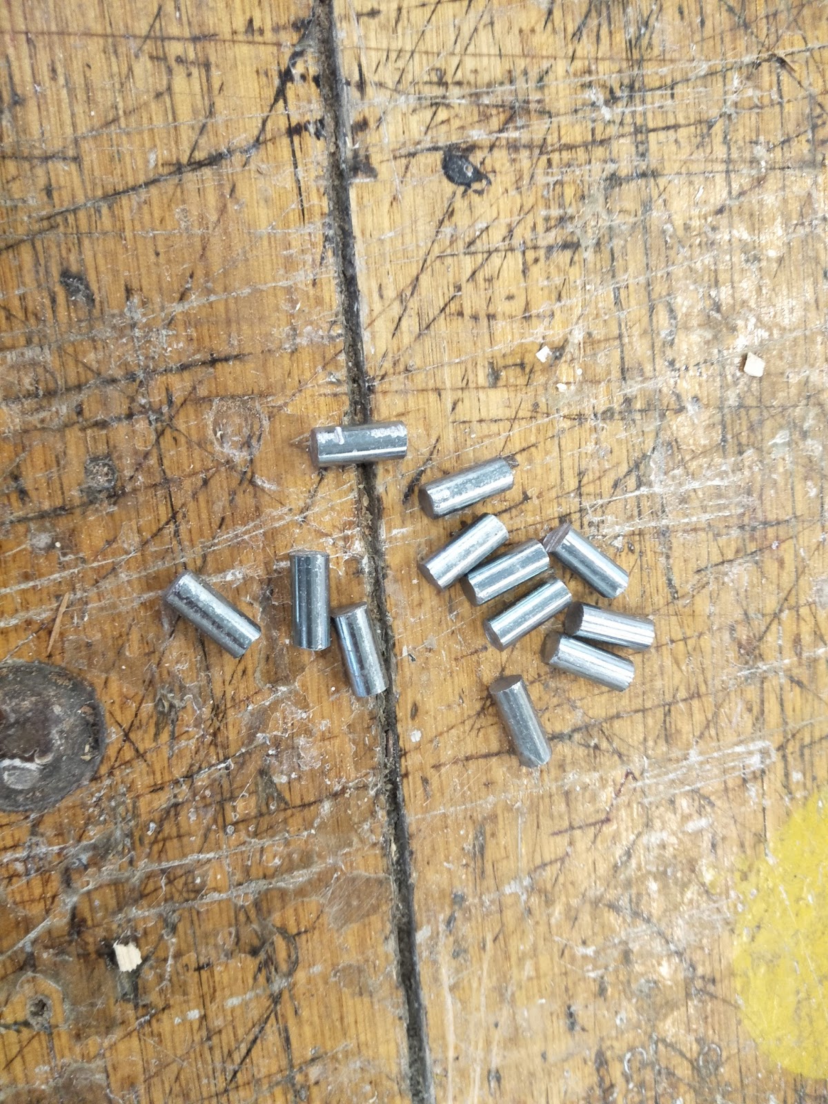
Hacksawed twelve 20mm lengths of steel and filed the edges down.

Glued them in with epoxy. I needed to spend more time ensuring they were straight.

I moved onto assembling the rest of the jacks, which included sanding down the 3D printed tongues (white part that pivots and holds the plectrum) so they fit comfortable in the jack and rotated back and forth freely. I started to make the plectrums from HIPS again, but the strings we situated a lot closer to the jack now than in the prototype, which didn't allow the plectrum to be long enough to bend. This resulted in a lot of force needed to press down on a key to make a noise. But I hooked it up to the amp (which worked no worries, I might add), and I noticed even the slightest touch of the strings were picked up and amplified. SO my solution to HIPS being too rigid? Use paper! I folded a small strip of paper enough to slot into the gap I left in the 3D printed part (so I could change out the plectrums later on) and tested the sound. Paper was perfect! Rigid enough to make a noise come out the amp and flexible enough so the keystroke needed barely any pressure at all.


I never implemented a spring to assist the tongue to return to it's original position because they did so without one. A spring would definitely be an improvement to the jack so it's something I intend to do at a later date.
While sanding the tongues I sanded a bit too far and ended up seeing red on the sand paper suddenly.

But no time for bandaids...


With nothing left to do but tune the strings, I used an air compressor in the workshop top clean out all the dust, plonked it on a trolley, and wheeled it up to studio for tuning.


The tuning pegs worked, the jacks worked, the plectrums worked, even the octave shifts worked. They took a lot of force to engage but they worked. I actually couldn't believe myself at this point. 10 weeks ago I would never have thought I'd product this model. Even through my whole build process, the image in my mind of the end result wasn't nearly as good as the actual end result. Which is a very unfamiliar experience.
I'm very satisfied with myself. I feel like I challenged myself to see if I was as clever as I thought I was. Challenges are good, they teach us so much about what we can do, and what things need work. If I were to chose some of the areas I need to improve on after this project would for sure be based around getting a high quality finish. I began the project putting in a lot of time and delicacy to get the pieces looking nice, but I really should have spent more time sanding EVERY face of EVERY component. This would have made the varnish/stain go on easier and maybe wouldn't have left such a gross fake tan effect. The were parts with globs of varnish built up, areas with glue clearly visible through the acrylic, the frame broke in 2 places while assembling but that was to be expected. By me at least.
If the slots in the base for the frames were just a quarter of a millimeter wider, It might have saved a lot of hammering.
Also the registers which hold the jacks in place could do with a tighter tollerance. The 8x15mm jacks were passing through 8.5x15.5mm rectangular holes in the registers. This gave them too much wobble and they sometimes pass the string without touching it.
But in retrospect, this is the best thing I've ever made. I have a bad habit of beginning extremely ambitious projects (daft punk helmet, 3 separate attempts) and abandoning them halfway through. But this Uni degree has forced me to stick to my guns and finish. That terrible, dreadful, constantly looming deadline really drives a man like nothing else. I don't know who's reading this blog but I'd really like to thank Dan and Andrew for all the advice they gave me down the track. Andrew had some really good ideas which carried into the final design and Dan gave me nothing but encouragement despite my idea being extremely ambitious. Gordo and Toby in the workshop are miracle makers, and I owe them a lot for all the help they gave me. Even Mac was helpful and had some great ideas. This has so far been a really enlightening course and it was throughout the duration of this project that I really got what I joined Product Design for.


I added dampers for each string to silence the vibration once the jack had returned to resting position. They're just a piece of dowel wrapped in felt.


And here's a couple videos, incase you made it to the end
Here it is with the highest octave mode engaged
-Luke Timpani